top of page

Custom Gear Profiles
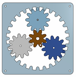
This was a partner project for my robotics class. The objective was to move a mario kart character 90 degreees while our motor spun 360 degrees. This required a gear train with a 4:1 ratio, and we were required to design our own gear profiles without using gear generators or CAD gear features. My partner and I chose to use a planetary gear system and tackle the added challenge of meshing that comes along with it.
Step 1: Meshing Gears
The first step we took in the project was testing multiple variations of custom teeth profiles. On the right you can see the first two iterations: one gear train with smaller teeth, and one larger and fewer teeth. We found that the smaller teeth had much better spacing and increased compatibility. All prototypes were made out of 3 mm acrylic to reduce friction between the gears.
Final System
My partner developed the ring gear and we put all the pieces together. We adapted the sun gear to fit the D shaft of our stepper motor and mounted the stepper motor into a piece of scrap wood. The fixed components of the design were the motor and the ring gear, which I nailed into the piece of wood.
Code and Electronics
We used an L289N motor driver and basic stepper code provided by our professor for this project. The motor was powered by a barrel jack power supply.
Step 2: Adjusting Gear Ratio
In step 1, we found a tooth profile and size that worked for us. Next, we set out to adjust the gear ratio to achieve our desired goal. Additionally, we started to troubleshoot the increased meshing challenges that come with planetary systems. For all of our preliminary testing, I included 2mm holes in the gears so that they could be nailed to scrap 2x4 that I planed to have a smooth surface. This allowed for easy adjustment of gear spacing during testing.
What did we learn?
We found that the ring gear required the sun gear to be very precisely centered in order for the planets to mesh evenly on all sides of the ring gear. To make this easier, we designed a cover for the system with a hole in the center that slots over the motor shaft and connects to the ring gear. The addition of the cover constrained the ring and sun gears to be concentric.
bottom of page