top of page

FEA Analysis of a Zipline
This analysis was part of a group project I completed for Materials and Manufacturing I, a class I took fall semester of sophomore year. I completed the majority of the Solidworks for this problem, but collaborated with my groupmates to discuss the FEA results.

.png)
.png)
.png)

.png)
We started by predicting the theoretical deflection and maximum stress. I then ran a motion analysis to find the stresses and deflections predicted by SolidWorks, and compared the results received.
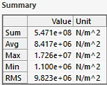
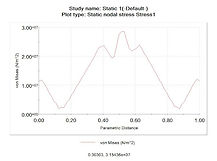
The maximum stress along the horizontal component of the rail is 1.726 x10⁷ Pa, or 17.26 MPa. The maximum calculated stress was 14.26 MPa. These are fairly similar results, and the discrepancies may be explained by a difference in mesh of our study versus the theoretical calculations that automatically accounts for this. Furthermore, the calculated stress is an average stress and therefore our stress may be higher due to variations in how the simulation calculates the force that takes into account where the force is applied. The same can be said for the variations in deflection, as seen below:
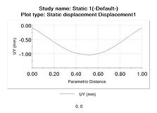
The FEA analysis found a maximum deflection of .775 mm compared to a calculated deflection of .33 mm. This discrepancy is partially a result of the entire structure being compressed (not just the beam). However, the variance in FEA deflection cannot all be attributed to this, and higher FEA deflection may also be a result of the way the simulation interprets the moment of inertia for irregular cross sections.
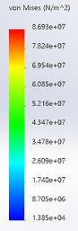
We noted that the rail is not the place in which there is the highest stress, rather, it is the horizontal connection of the wheels to the handle that allows the handle to move that experiences the highest stress. This is likely due to the fact that it experiences the load directly and also experiences the normal force from the rail that holds it in place. We classified this structure as extremely safe; the maximum stress experienced as found in the von Mises colored key is 57.32 MPa. The yield stress is 620 MPa so the structure is not in any danger of yielding. Worth noting is that this simulation is being run under a force of 1200 N, or supporting the weight of a 120 kg (264 lb) person; a larger load than that applied by a typical user of this structure (a child).
We identified parts of the handle (shown right) as experiencing the highest stress. One thing that we noticed was that the connection of the support to the handle is filleted, while the connection to the wheel is not. The stress only concentrates where the support is not filleted, so changes that could be made to distribute the stress near the wheel would help to reduce the overall stress. One change that could be made is increasing the thickness of the connector of the handle and the wheels. Adding a fillet on the other side (closer to the wheel) would help to distribute the force over a larger area. However, this may be difficult as it could interfere with the spinning of the wheels. Another place that stress concentrates is at the corner of the handle and this could be reduced by increasing the thickness of the handle.
Next, I changed the material from alloy steel to aluminum 1060 alloy. This change was made as a potential suggestion to reduce cost, and the change needs to be evaluated for safety.
.png)
.png)

.png)
.png)
.png)
.png)


The aluminum 1060 alloy has a yield strength of 27.57 MPa and the maximum von Mises stress found in the FEA analysis along the top edge of the rail was 13.38 MPa. Note that the maximum stress found in the FEA was 86.9 MPa but this is not found in the aluminum, it acts on the alloy steel handle. The deflection found with an aluminum rail was 1.37 mm at its maximum. Originally, we wanted to approve this switch given the safety factor of >2 for the rail. Later, we discovered that this is not enough for children's play structures.
When considering this change, we kept in mind that we are changing the rail, not the handle. The handle experiences the greatest stress, but the material of the handle would remain alloy steel, which has a yield strength of 620 MPa. Aluminum has a lower carbon footprint in comparison to steel, which makes it more desirable long term. Despite the environmental advantages of aluminum in comparison to steel, we were unable to approve this material change given children's play structure's safety factor requirements.


An alternative suggestion to lower cost was to reduce the thickness of the rail from 4 centimeters to 2 centimeters while keeping alloy steel as the zipline material.
We found that the maximum stress experienced by the beam is 28.59 MPa. The maximum deflection for the beam is 1.04 mm. We would approve this change based on the deflection and the stress as compared to our original results. We had previously found a stress of 17.26 MPa and a deflection of .775 mm. Our results did not drastically changed with a thickness reduction and with a yield stress of 620 MPa (a safety factor of >20) we would still consider this structure extremely safe.
The beam experiences notable higher stress with a reduction in thickness, but we approved of this change as a cost reduction strategy based on the high yield stress of alloy steel.
bottom of page