top of page

Tank
This project was completed in a group for my electronics and controls class. The objective was to create a wireless robot that can go up a ramp and carry a payload. Our tank was controlled using a Raspberry Pi that received signals through the internet.

On the right is our tank with its lid removed. Inside, you can see the RaspberryPi, an L298N dual H-bridge motor driver, the 11.1 V battery we used to power our motor, a portable charger used to power our RaspberryPi, and our motors. The top of the tank is flat to carry a payload.
The body of the tank is made primarily out of aluminum sheet metal, but the top is matte black acrylic that we laser cut to serve as the lid. The top needed to be acrylic so that we could control our RaspberryPi wirelessly through the internet. If the top was metal, this would create a faraday cage, blocking our tank from receiving signals.
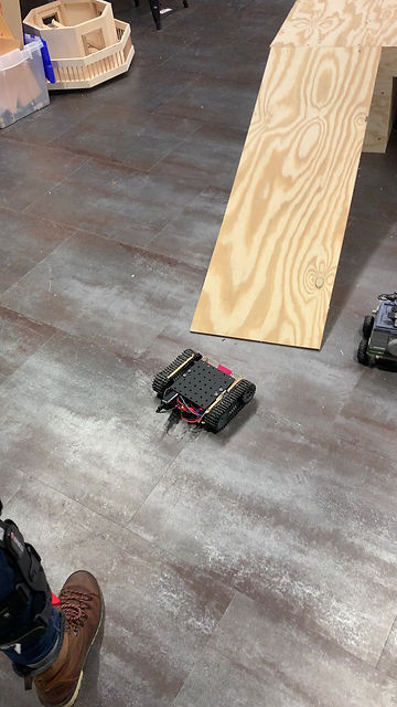
Below is our tank successfully completing the ramp.

Getting Traction
The most difficult part of this assignment was getting enough traction between our treads and the ramp. We had multiple different approaches to this problem.
Rubber Cement
Our first plan was to paint rubber cement onto the treads. This was initially very effective, but after going up the ramp a handful of times, the stickiness on the treads wore off, and our tank would no longer make it up.
Rubber Bands
To combat this, we stretched rubber bands over our treads. This helped with the traction, but due to the pressure on the treads the tank would heavily veer left.
Rubber Bands Part II
The traction on the rubber bands encouraged us to keep trying. To reduce the compression on the treads, we cut the rubber bands into pieces and tied them to the treads using fishing line. Unfortunately this did not help as much as we anticipated. Our left tread had slightly more slack in it, so even with the reduction of compression, our tank still veered left.
Results
To the left, you can see the results of our rubber band experiments. The tank has good traction, but drives left off of the ramp. In our experiments, the tank fell off the ramp many times and proved itself very resilient to impact. It also made it to the top and was driven off by accident, landing upside down, and continued to drive well after being flipped over. Ultimately, we decided that the rubber cement provided the best balance of traction and steering, even if it needed to be reapplied. These experiments highlighted our tanks resilience, and we were very pleased with our tanks performance when subjected to impact.
Building the Body
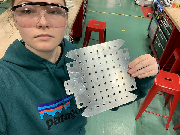
The body of our tank was made out of scrap aluminum sheet metal. I designed the shape of the body using OnShape, and used a water jet to cut it out. There were multiple iterations of the body, but the final iteration can be seen on the right. The design has many mounting holes, larger holes for the motors, and cuts that allow the front and back of the tank to be bent up.
Bending
After cutting out our shape, we bent the body using a table bender and the bending portion of the 3 in 1 shear. The smaller tabs are for mounting the lid, and those were bent by hand.
More About the Electronics
Code
This project was run using a RaspberryPi microcontroller. We controlled our steering by being able to turn on the right and left motors individually. We connected our RaspberryPi to the Internet and were then able to log in from Terminal on our computer and run python code wirelessly. Our code was very straightforward, it ran a while loop that continuously checked for keyboard inputs (f, ff, b, l, r, q) which were forward, long forward, back, left, right, and quit. These commands turned both motors on for .5 seconds to go forward or backwards, and long forward was 2 seconds. To turn, we had one motor run forwards and the other backwards, which allowed the tank to turn without moving forwards. For a turn, the motors turned on for a quarter of a second (about 15 degrees).
Electronics
When the RaspberryPi receives a command from the Terminal, what it is really being told is to send voltage to a specific output pin (set the pin high). The pins are connected to our H-bridge; setting a pin high sends the H-bridge voltage to turn the motor on. Which pin is set high dictates which motor is turned on and in what direction. Each of our motors has three states: forward, backward, and off. We used an L298N dual H-bridge motor driver, which had five connections to our RaspberryPi: two directions for each motor and a ground connection. Our biggest debugging problem was that our initial motor driver had a broken connection that needed to be identified using a multimeter.
bottom of page